How Remote Digital ATC Towers Work Technically
A look at the cameras, fiber, and displays replacing the glass cab.

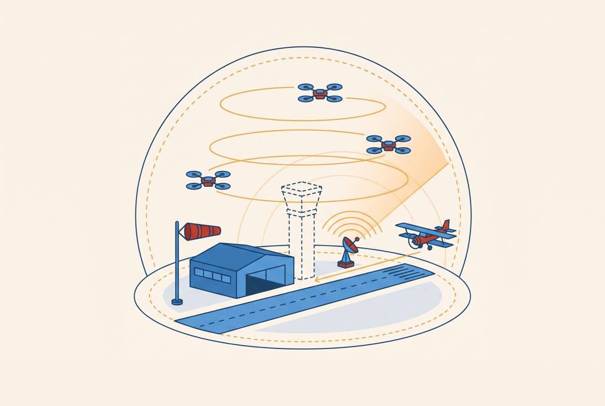
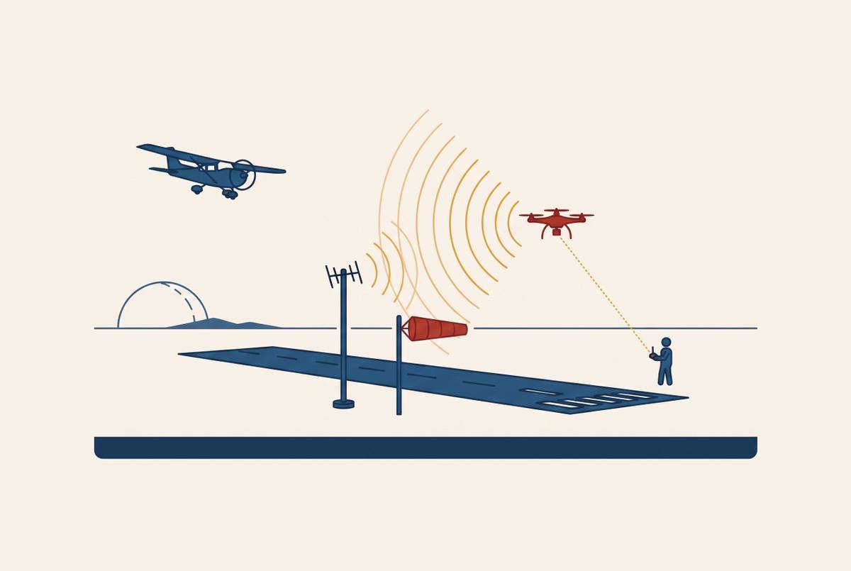
Digital ATC towers use cameras, sensors, fiber networks, and displays for controllers to provide tower services without a conventional glass cab. For non-towered airports considering drone integration, this architecture offers a foundation for controller situational awareness. It pairs an augmented view of the airport with infrastructure and staffing that small airports can support.
What a digital ATC tower actually is, and why the FAA renamed it
The FAA defines Digital Airport Traffic Control Tower Systems (DT Systems) as technology that uses cameras, sensors, displays, and support equipment to provide Airport Traffic Control Tower (ATCT) services. The agency is replacing “Remote Tower” with “Digital Tower” because the defining feature is digital observation. A Digital Tower Center (DTC) can be on or off airport property, though both terms remain in older materials while the official documents are updated. In either location, the core substitution is the same, with controllers receiving the visual information previously gathered through tower windows entirely through dedicated digital displays.
The sensing layer: cameras, infrared, and the mast that replaces the glass cab
The FAA’s infrastructure guidance allows cameras to be installed on existing or stand-alone infrastructure. A mast or pole supports the cameras and sensors that replace the controller’s elevated viewpoint, rather than requiring a building with an occupied glass cab. Camera placement establishes the airport’s visual coverage. High-definition cameras face arrival and departure paths, runway thresholds, and ramp areas to provide a full 360-degree view of the aerodrome and its surroundings. The architecture therefore separates the structure needed for observation from the space needed for controllers to work.
Within that coverage, controllers can zoom in on points of interest, including an aircraft on final approach or wildlife on a runway. Fine detail need not depend on unaided eyesight. A controller in a conventional cab would need binoculars for a comparable closer view, while the digital system provides magnification through the camera feed. This capability complements the panoramic view rather than substituting a narrow image for the surrounding airport scene.
The FAA says optical sensors may include day/night cameras or infrared/thermal cameras, and does not describe infrared as a feature of every HD camera. Thermal imagery can extend visibility at night and in bad weather beyond what an unaided observer sees through glass. The mix of sensors can vary, but each setup must give the controller visual information they can use.
The transmission layer: how video and data move from mast to controller without delay
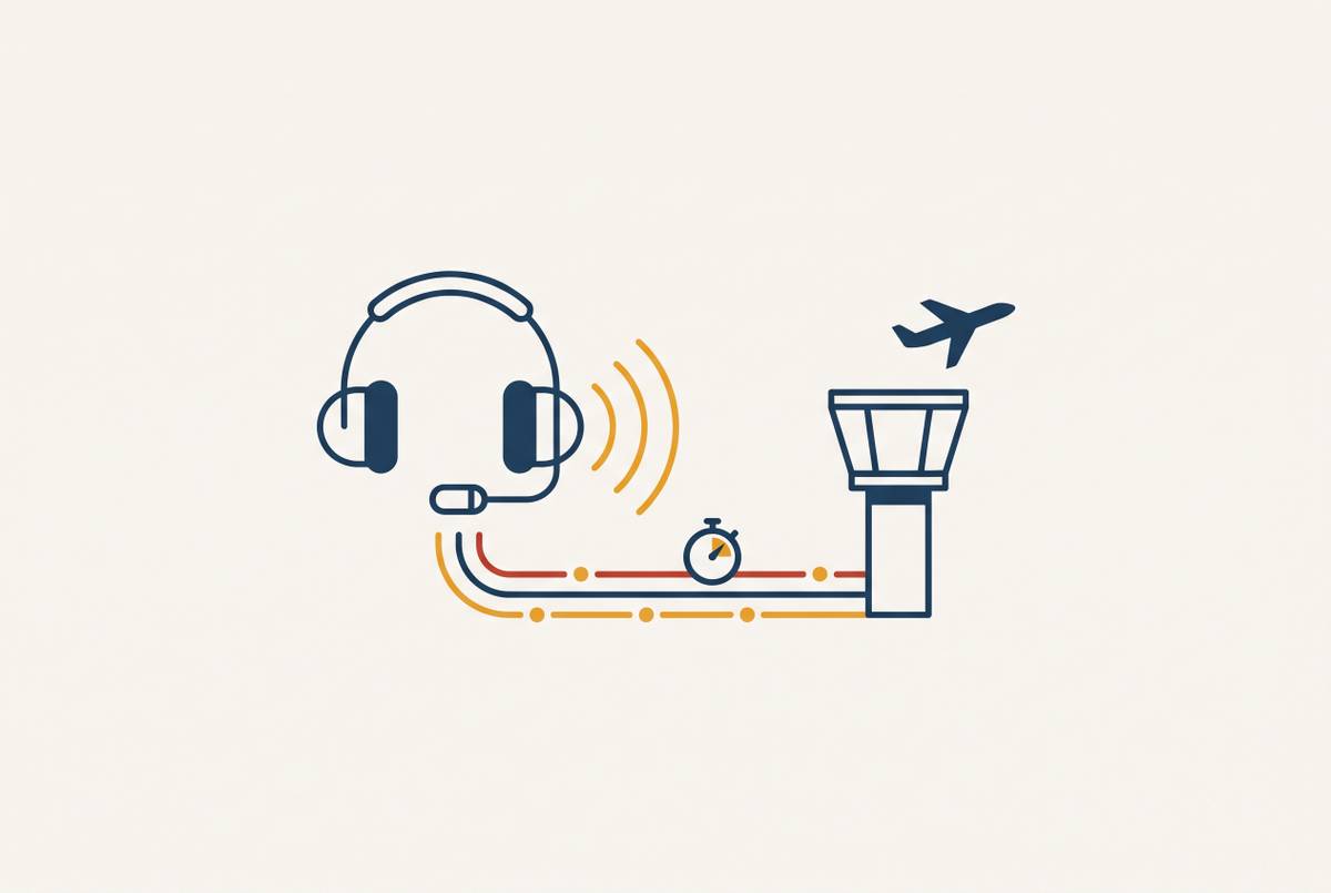
The FAA currently requires all data transfer to use a closed, physically point-to-point network, with an independent fiber optic telecommunications feed between the sensors and the DTC. The current requirement for fiber optic communication reflects the dependence of tower operations on timely, reliable visual information. A controller cannot work from an airport picture that arrives with an operationally unacceptable delay. Fiber provides the prescribed transport architecture, although low latency should not be confused with a claim of literally instantaneous transmission.
The closed link also establishes a defined cybersecurity boundary. Physical isolation makes the connection harder to attack than an IP network exposed to the internet, without implying that isolation removes every security concern. This is a deliberate design constraint. Because the DTC need not be beside the mast, the fiber connection can also support a center serving multiple airports, establishing the network basis for shared operations. Funding rules still constrain location, since DT Systems supported by the Airport Improvement Program or other applicable grants must be on airport-owned property or property leased to the Airport Sponsor.
The display layer: what the controller sees and how augmentation improves on the view from the cab
The display environment turns the sensing and transmission layers into a working airport panorama. In the described DTC layout, a semi-circular room at ground level has high-definition screens mounted in portrait orientation across its walls, extending from top to bottom. Compression technology fits the view of the airport and its surroundings onto this wide arc. The format preserves spatial orientation for the controller. Rather than arranging disconnected camera images as unrelated views, the display reproduces the angular sweep used to understand where activity is occurring around the aerodrome.
Each aircraft within visual range can be tagged with its tail number, much as identification appears on a radar display. Runway conditions, weather, and traffic information can also be overlaid on live video without requiring a switch to another view. Compared with a conventional cab, the controller can therefore have both the visible scene and relevant operational data in the same field of attention.
Eurocontrol describes AI-assisted capabilities that can add another layer of support to this display. Vision systems can track aircraft, vehicles, and people across the airfield, while anomaly detection can flag possible problems with the landing gear or flap configuration. These tools help controllers, who still have to use their own judgment. Machine learning can also analyze historical traffic patterns and real-time data to identify potential conflicts and suggest resolutions. Such capabilities extend the information available to a controller, but they should not be read as a claim that every deployed system includes every AI function.
The comparison with a glass cab is consequently specific. Infrared lets controllers see more at night than they can with unaided night vision, zoom gives them a closer look, and labels identify the aircraft they can see. Overlays let controllers check related information while watching the live scene, and AI-assisted warnings can alert them to conditions as they develop. The controller remains responsible for interpreting that information.
How the FAA's certification process governs what can be deployed and where
The FAA is first bringing DT Systems to airports in Class D airspace through Airport Sponsor-owned Non-Federal Control Towers and FAA Contract Towers. Its pathway also includes airports in Class E and G airspace that wish to transition to Class D. That provision reaches beyond replacing existing towers. It allows an airport without tower services to pursue them through a digital installation, subject to the applicable approval process. Deployment at federally owned ATCTs requires additional FAA work on the requirements for federal implementation.
System Design Approval is the formal gate for operation in the National Airspace System (NAS). The process is demanding because the system supplies the visual information on which controllers base operational decisions. Vendor systems have been required to undergo testing and evaluation at the William J. Hughes Technical Center near Atlantic City, New Jersey. The FAA Reauthorization Act of 2024, Section 621, directs the agency to allow testing at no fewer than three airports outside the Technical Center as well. This allows testing at more sites, but the systems must still be shown to be safe.
The FAA has issued a Request for Proposals outlining potential procurement of up to 50 digital tower units over five years. The FAA Flight Plan 2026 also names deployment of digital remote tower technology at the first key site as a goal. Neither statement establishes that those deployments are complete.
What national policy and funding have now made possible
Federal legislation has set aside money for digital towers as part of a wider program to modernize airspace. The Department of Transportation and FAA’s Brand New Air Traffic Control System (BNATCS) initiative includes new digital towers at some non-towered airfields. It also covers replacement of radios and control equipment across hundreds of ATC facilities while daily operations continue. Digital towers are therefore part of a larger infrastructure undertaking. Their role is not confined to an isolated demonstration or a replacement project at an existing towered airport.
Some NAS analog radio and communications equipment is more than 30 years old, creating a modernization need independent of the choice between conventional and digital towers. Moving from outdated copper lines to fiber networks supports the transport medium DT Systems require. Federal backing aligns public investment with the communications and tower technology needed for deployment, while site-specific design, testing, and approval obligations remain.
How Norway's NINOX program demonstrates the multi-airport operating model at scale
Avinor’s NINOX program provides an operational example of the shared-center model across a national airport network. Avinor is implementing remote tower services at 21 airports from a tower center in Bodø, in what is described as the world’s largest multi-airport digital tower program initiative. The model is already supporting daily operations. Its significance lies in the connection between airport sensing equipment, remote presentation, and a common controller workplace.
Within that model, a single controller can manage multiple low-density airports from one center. This demonstrates an operating arrangement that the fiber-linked architecture permits but does not, by itself, guarantee. Traffic density is central to the example. The program’s continued expansion, driven by a board decision, also shows an operator choosing to extend a model with which it has operational experience. Implementation across 21 airports should not, however, be confused with a claim that every planned airport is already in service.
Norway’s example does not establish that FAA requirements are identical or that a particular U.S. installation will qualify for service. One center can support real operations at multiple airports, including shared controller coverage where the traffic permits it. That shared setup can help airports with too little traffic to justify the infrastructure and staffing of a conventional tower.
Why digital towers are the practical answer for the airports that have never had a tower at all
Conventional FAA towers can cost between $30 million and $100 million to build, while the digital tower system itself costs a fraction of that. A mast also requires far less civil construction than a traditional tower building. The comparison is not a complete project budget. Fiber connections, a controller workplace, and the approval process remain part of deployment, but the architecture removes the need to elevate an occupied cab above the airport. That changes the construction proposition for an airfield that has never been able to support a conventional facility.
A multi-airport DTC can reduce the per-airport staffing burden at low-density locations, as the operating model described above demonstrates. Geography becomes less restrictive for controller recruitment. Controllers can work at one center that serves several airfields without having to live near each airport, which matters for rural and remote communities. The practical benefit comes from combining a smaller physical installation at each airport with a staffing arrangement based at a common center.
For airports considering nearby drone operations, the supported technical proposition is enhanced controller awareness through panoramic sensing, live video, identification, and operational overlays. The notes establish tower infrastructure. That distinction keeps the deployment case precise. The FAA’s Class E and G to Class D pathway supplies the route from an uncontrolled airport to controlled-airspace operations without a conventional tower building, and digital tower providers such as General Aviation, a US-based maker of remote tower systems for small airfields where drone activity is rising but oversight is thin, build their offerings around that route.